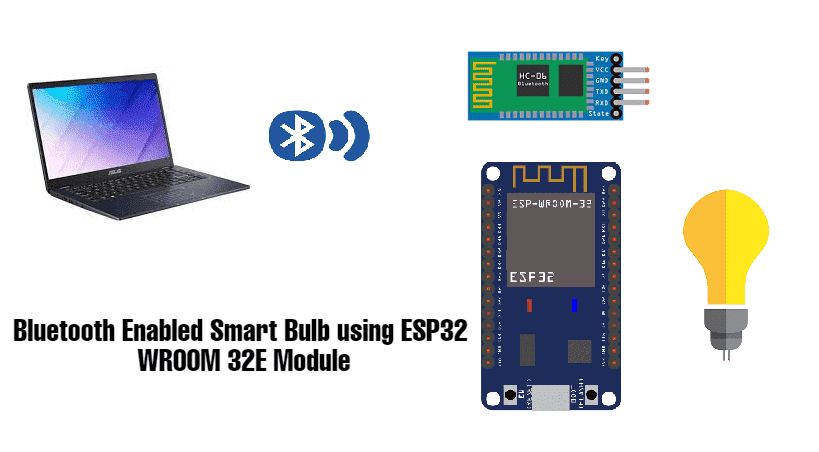
In the ever-evolving landscape of smart home technology and IOT, One great application is Bluetooth-enabled smart bulb using the ESP32 Wroom-32E module.
In this article we will see a tutorial to build a Bluetooth enabled Smart Bulb using ESP32 Wroom 32E Module. This innovative project allows you to control your home lighting system effortlessly via your smartphone. In this blog post, we'll explore the key components, functionalities, and step-by-step guide to building your own wireless bulb.
An ESP32 microcontroller can be used to control a light bulb over Bluetooth by using a relay to switch the power to the bulb on and off. The ESP32 can be programmed to listen for Bluetooth commands and use its digital output pin to control the relay.
Let’s now discuss the construction requirements for this project:
Components Needed For This Project
And, Bluetooth enabled Smartphone
Building the Circuit:
Connect the (-) pin of the relay to the GND pin of the ESP32 board
Connect the (+) pin of the relay to the 3.3V pin of the ESP32 board
Connect the (S) pin of the relay to the GPIO23 pin of the ESP32 board
Connect the (ON) pin of the relay to one of the lamp terminals
Connect the (COM) pin of the relay to the electrical source
Connect the other terminal of the lamp to the electrical source.
Complete code:
#include "BluetoothSerial.h"
#if !defined(CONFIG_BT_ENABLED) || !defined(CONFIG_BLUEDROID_ENABLED)
#error Bluetooth is not enabled! Please run `make menuconfig` to and enable it
#endif
BluetoothSerial SerialBT;
int received;// received value will be stored in this variable
char receivedChar;// received value will be stored as CHAR in this variable
const char turnON ='a';
const char turnOFF ='b';
const int LEDpin = 23;
void setup() {
Serial.begin(115200);
SerialBT.begin("Campus_Component"); //Bluetooth device name
Serial.println("The device started, now you can pair it with bluetooth!");
Serial.println("To turn ON send: a");//print on serial monitor
Serial.println("To turn OFF send: b"); //print on serial monitor
pinMode(LEDpin, OUTPUT);
}
void loop() {
receivedChar =(char)SerialBT.read();
if (Serial.available()) {
SerialBT.write(Serial.read());
}
if (SerialBT.available()) {
SerialBT.print("Received:");// write on BT app
SerialBT.println(receivedChar);// write on BT app
Serial.print ("Received:");//print on serial monitor
Serial.println(receivedChar);//print on serial monitor
//SerialBT.println(receivedChar);//print on the app
//SerialBT.write(receivedChar); //print on serial monitor
if(receivedChar == turnON)
{
SerialBT.println("LED ON:");// write on BT app
Serial.println("LED ON:");//write on serial monitor
digitalWrite(LEDpin, HIGH);// turn the LED ON
}
if(receivedChar == turnOFF)
{
SerialBT.println("LED OFF:");// write on BT app
Serial.println("LED OFF:");//write on serial monitor
digitalWrite(LEDpin, LOW);// turn the LED off
}
}
delay(20);
}
After Compiling successfully the above code in Arduino IDE upload it to ESP32 Wroom 32E module
Working Process
You program your ESP32 microcontroller using Arduino IDE or another compatible environment.
The code includes configurations for Bluetooth communication.
In code, we define Bluetooth characteristics. For example, "LED Control" to represent the state of the LED (on/off).
Here we will use a Bluetooth Terminal app on a smartphone.
The app discovers nearby Bluetooth devices, including your ESP32, and establishes a connection.
In the app after pairing with ESP32, we will send “turnON” and “turnoff”.
When a user sends the functions in the app to control the LED, the app sends a command over Bluetooth to the corresponding characteristic on the ESP32.
The ESP32 receives the Bluetooth command.
ESP32 firmware processes the command and updates the GPIO pin connected to the LED based on the received command.
For example, if the command is “turnON”, the code sets the GPIO pin high to turn on the LED.
The state of the LED is now controlled by the ESP32 in response to Bluetooth commands from the smartphone app.
If the user sends “turnoff”, the app sends a command to the ESP32, which updates the GPIO pin to turn off the LED.
You can now test the setup by interacting with the smartphone app and observing the corresponding changes in the LED's state.
That’s it you finally made an IoT project where we can control the Bulb wirelessly using ESP32’s Bluetooth.
Conclusion
In this blog post, we've learned how to create a Bluetooth-enabled smart bulb using the ESP32 Wroom 32E module. With the right components, programming skills, and a passion for innovation, you can build more applications as needed.
We can make different projects using ESP32 Wroom 32E Bluetooth module, eg. in smart agriculture, smart homes, and many applications related to large industries.If you are looking for electronic components and different microcontrollers from Espressif, Arduino, and many more, reach out to electronics components suppliers in india- Campus Component today!
