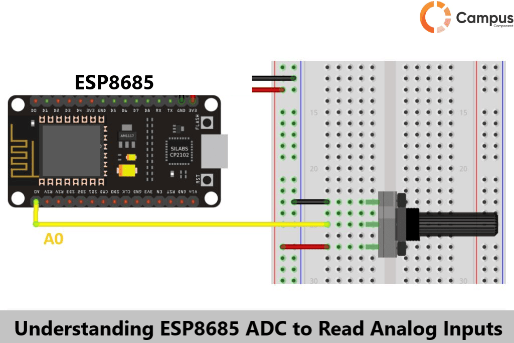
With the rapid advancement of embedded systems and the Internet of Things (IoT), the ESP8266/ESP32 series of Wi-Fi modules has gained popularity due to its user-friendliness and cost-effectiveness. Recently, Espressif introduced its successor, the ESP8685 Wi-Fi module, an upgrade to transform the world of connected devices.
The ESP8685 microcontroller is a powerful microcontroller for IOT projects. One of the key features of the ESP8685 is its Analog-to-Digital Converter (ADC), which allows it to read analog inputs. In today's article we will understand the ESP8685 ADC, we will discuss how it works and how we can effectively use it in your projects.
ESP8685
ESP8685 is a powerful, generic Wi-Fi and Bluetooth LE module that has a rich set of peripherals and ultra-low-power, highly integrated SoC solution based on an MCU. This controller is suitable for a wide range of applications, including smart home devices, industrial automation, wearables, and various other IoT applications.
Pin Layout of ESP8685:
The diagram below shows the pin configuration of the ESP8685:
The ESP8685 comes with an ultra-low-power SoC with a RISC-V single-core CPU, supporting IEEE 802.11b/g/n (2.4 GHz WiFi). It comes with either 2MB (ESP8685H2) or 4MB (ESP8685H4) flash memory in a compact 4×4mm QFN package.
For a more detailed understanding of the architecture, please refer to the ESP8685 datasheet.
Let’s discuss the Features of ESP8685:
WIFI
The ESP8685 complies with IEEE 802.11b/g/n WiFi standards.
It supports 20MHz and 40MHz bandwidths in the 2.4 GHz frequency range.
Includes Wi-Fi Multimedia (WMM) functionality.
CPU and Memory
Powered by a 32-bit RISC-V single-core processor, capable of running up to 160MHz.
Core Mark® score: – 1 core at 160 MHz achieves 407.22 Core Mark, equating to 2.55 Core Mark/MHz.
Equipped with 384KB ROM.
Contains 400 KB SRAM, with 16KB reserved for cache.
Advanced Peripheral Interfaces
Includes 15 programmable GPIOs.
Digital interfaces:
• 3× SPI (with SPI0 and SPI1 used for connecting the SiP flash, leaving SPI2 available for use).
• 2× UART
• 1× I2C
• 1× I2S
• Remote control interface featuring 2 transmit channels and 2 receive channels.
• LED PWM controller supporting up to 6 channels.
• Full-speed USB Serial/JTAG controller.
Analog interfaces:
• 2× 12-bit SAR ADCs, supporting up to 6 channels.
• 1× temperature sensor.
Timers:
• Features with 2× 54-bit general-purpose timers.
• Has 3× watchdog timers.
• Featuring 1× 52-bit system timer.
Security
• Features secure boot technology.
• Supports flash encryption.
• Includes a 4096-bit OTP, with up to 1792 bits available for use.
• Offers cryptographic hardware acceleration.
What is an ADC (Analog-to-Digital Converter)?
An Analog-to-Digital Converter (ADC) is an electronic device that converts analog signals into digital signals. This process is crucial for microcontrollers, which operate in the digital domain, to interface with the analog sensors or values. Sensors like temperature sensors, light sensors, and potentiometers typically output analog signals, which need to be converted to digital to be processed by the microcontroller.
Key Features of the ESP8685 ADC
10-bit resolution: This provides 1024 different values for representing the analog input, allowing for accurate readings.
Multiple input channels: The ESP8685 ADC supports multiple pins, enabling it to read signals from various sensors.
High sampling rate: This ensures that the ADC can quickly convert analog signals to digital values, which is essential for real-time applications.
How the ESP8685 ADC Works
The ADC on the ESP8685 works by reading the analog input signal at regular intervals and converting these samples into digital values. The 10-bit resolution means that the input voltage is divided into 1024 discrete levels, providing a digital output that corresponds to the analog input voltage.
How to use the ESP8685 ADC:
Setup the ADC: Initialize the ADC in your code, specifying the pin to which your analog sensor is connected.
Read the analog input: Use the appropriate function to read the analog value from the specified pin.
Process the data: Convert the raw digital value to a meaningful physical quantity (e.g., temperature, light intensity) based on the sensor's characteristics.
Let's read Analog value from Potentiometer:
Hardware Setup:
Connect the middle pin of the potentiometer to an analog input pin on the ESP8685 (e.g., GPIO36).
Connect the other two pins to VCC (3.3V) and GND, respectively.
Code:
#include <Arduino.h>
const int potPin = 36; // Pin connected to the potentiometer
void setup() {
Serial.begin(115200);
analogReadResolution(10); // Set ADC resolution to 10 bits
}
void loop() {
int potValue = analogRead(potPin); // Read the analog value
float voltage = potValue * (3.3 / 1023.0); // Convert to voltage
Serial.print("Analog Value: ");
Serial.print(potValue);
Serial.print(" - Voltage: ");
Serial.println(voltage);
delay(500); // Wait for half a second before the next reading
}
Applications of ESP8685
• Smart Home
• Industrial Automation
• Health Care
• Consumer Electronics
• Smart Agriculture
• Audio Device
Conclusion:
The ESP8685 is combined with advanced features, low power consumption, and affordability, making it a good choice for embedded/IOT developers. For those working with analog inputs, the ESP8685 ADC is an invaluable tool. Whether your project involves a simple potentiometer or multiple sensors, understanding how to use the ADC effectively is important. By following the above article, you can accurately read and process analog signals.
Also refer to the ESP8685 datasheet to fully understand capabilities and limitations of the ADC. For all your microcontroller needs, including the ESP32, ESP8266, ESP8685, and other electronic components, visit Campus Component today.
